
TEM6 Installation Manual: A Comprehensive Guide
This manual details the TEM6 series air handler installation‚ maintenance‚ and operation‚ ensuring optimal performance and compliant setup for professionals and homeowners.
The TEM6 is versatile‚ suitable for closets‚ utility rooms‚ basements‚ or attics‚ and applicable to both air conditioning and heat pump systems.
The TEM6 series represents a significant advancement in convertible air handler technology‚ designed for a wide range of applications and installations. These units‚ ranging from 2 to 5 tons‚ offer exceptional versatility‚ accommodating both air conditioning and heat pump systems with ease.
Engineered for adaptability‚ the TEM6 is suitable for diverse locations including closets‚ utility rooms‚ alcoves‚ basements‚ crawlspaces‚ and attics. This flexibility simplifies installation in various residential and commercial settings. The series incorporates features aimed at maximizing efficiency and minimizing operational costs‚ contributing to long-term savings for end-users.
This manual provides comprehensive guidance for installers and technicians‚ ensuring proper setup‚ operation‚ and maintenance. Understanding the specific features and requirements outlined herein is crucial for achieving optimal performance and extending the lifespan of the TEM6 air handler. Referencing the included dimensional and electrical data is essential for a successful installation.
Safety Precautions
Prior to commencing any installation or maintenance procedure on the TEM6 series air handler‚ strict adherence to all safety guidelines is paramount. Electrical shock hazard exists; disconnect all power sources before accessing internal components. Qualified personnel only should perform electrical connections‚ ensuring compliance with local and national electrical codes.
Wear appropriate personal protective equipment (PPE)‚ including safety glasses‚ gloves‚ and appropriate footwear. Refrigerant handling requires EPA certification; follow all regulations regarding refrigerant recovery and disposal. Be mindful of sharp edges and potential pinch points during installation.
Proper lifting techniques are essential to prevent injury when handling the unit. Ensure the installation area is well-ventilated. Always consult the complete installation manual for detailed safety instructions and warnings. Failure to follow these precautions could result in serious injury or equipment damage.
Pre-Installation Considerations
Before installation‚ verify suitable location‚ adequate clearance‚ and confirm all TEM6 unit components are present and undamaged for optimal performance.
Unit Location Requirements
The TEM6 series air handler exhibits remarkable installation flexibility‚ readily adapting to diverse indoor environments. Acceptable locations include closets‚ utility rooms‚ alcoves‚ basements‚ crawlspaces‚ and attics‚ offering convenience for various building layouts.
However‚ careful consideration must be given to ensure proper operation and accessibility. Avoid locations exposed to direct sunlight‚ excessive moisture‚ or extreme temperatures. The chosen area should provide ample space for servicing and maintenance‚ allowing technicians easy access to all components.
Furthermore‚ the floor must be level and capable of supporting the unit’s weight‚ including the weight of any accumulated condensate. Ensure adequate ventilation to prevent overheating and maintain optimal performance. Prioritize locations that minimize ductwork length and bends to maximize airflow efficiency.
Clearance Requirements
Maintaining adequate clearances around the TEM6 air handler is crucial for safe operation‚ efficient servicing‚ and adherence to local codes. A minimum of 18 inches of unobstructed space should be provided in front of the unit to allow for convenient access to components requiring routine maintenance‚ such as filters and electrical connections.
Similarly‚ a clearance of at least 12 inches should be maintained on all sides and above the unit to ensure proper airflow and prevent restrictions. When installed in an attic or crawlspace‚ ensure sufficient headroom for technicians to comfortably work around the unit.
Avoid placing the air handler near combustible materials or obstructions that could impede airflow. Always consult local building codes for specific clearance requirements in your area‚ and prioritize safety when determining the final installation location.
Checking Unit Components
Before commencing installation‚ a thorough inspection of all TEM6 unit components is essential to identify any shipping damage or missing parts. Carefully unpack the air handler and compare the contents against the packing list to ensure everything is accounted for.
Visually inspect the cabinet for dents‚ scratches‚ or other signs of physical damage. Examine the coil for bent fins or obstructions. Verify that all electrical components‚ including the motor and wiring‚ are intact and properly connected.
Confirm the presence and correct sizing of the thermal expansion valve (TXV) kit‚ if applicable. Document any discrepancies or damage immediately and contact the manufacturer for replacement parts before proceeding with the installation. A pre-installation check saves time and ensures optimal performance.

Installation Procedure
Proper installation of the TEM6 series requires careful adherence to these guidelines‚ encompassing mounting‚ electrical connections‚ refrigerant lines‚ and condensate drainage.
Mounting the Air Handler
Securely mounting the TEM6 air handler is crucial for stable operation and minimizing vibration. The unit is designed for versatile installation locations‚ including closets‚ utility rooms‚ alcoves‚ basements‚ crawlspaces‚ and attics. Before mounting‚ verify the structural integrity of the chosen surface to support the unit’s weight‚ considering both the air handler itself and any added components like refrigerant lines or ductwork.
Ensure the mounting surface is level. Use shims if necessary to achieve a perfectly horizontal position. Utilize appropriate fasteners – screws‚ bolts‚ or anchors – suitable for the mounting surface material. Follow the manufacturer’s recommendations for fastener size and type. Maintain adequate clearance around the unit for servicing and airflow‚ as detailed in the ‘Clearance Requirements’ section. Proper mounting prevents noise transmission and ensures long-term reliability of the TEM6 system.
Electrical Connections
Prior to making electrical connections‚ disconnect power to the circuit at the breaker panel. Verify all electrical work complies with local codes and regulations. The TEM6 air handler requires proper grounding for safety and optimal performance. Use appropriately sized wiring‚ as specified in the ‘Electrical Data’ section‚ to handle the unit’s current draw.
Connect the power supply wires to the designated terminals on the unit’s control panel‚ carefully matching the voltage and polarity. Securely tighten all connections to prevent loosening due to vibration. Double-check wiring before restoring power. Incorrect electrical connections can damage the unit and pose a safety hazard. Refer to the wiring diagram provided with the unit for specific connection details.
Refrigerant Line Connections
Refrigerant line connections must be performed by a qualified HVAC technician. Ensure the refrigerant lines are properly sized and insulated according to local codes and manufacturer specifications. Before connecting lines‚ carefully inspect for any damage or debris. Use appropriate brazing techniques and materials compatible with the refrigerant type used in the system.

After brazing‚ perform a nitrogen pressure test to verify the integrity of all connections and prevent leaks. Evacuate the system thoroughly to remove any air or moisture before charging with refrigerant. Improperly sealed refrigerant lines can lead to system inefficiency and environmental damage. Refer to the unit’s technical specifications for the correct refrigerant charge amount.
Condensate Drain Installation
Proper condensate drain installation is crucial to prevent water damage and maintain system efficiency. The condensate drain line must have a continuous downward slope to facilitate proper drainage. Use PVC or other approved materials for the drain line‚ ensuring it’s adequately supported to prevent sagging or kinking.
A trap should be installed in the drain line to prevent air from entering the system and to help maintain proper water flow. The drain line termination point must be accessible for cleaning and inspection. Avoid connecting the drain line directly to the sewer system; instead‚ use an indirect connection with an air gap. Regularly inspect the drain line for clogs and address them promptly to avoid water overflow.
Air Duct Connections
Securely connect ductwork‚ ensuring proper sizing and sealing to maximize airflow efficiency and minimize energy loss within the TEM6 system.
Ductwork Sizing
Proper ductwork sizing is crucial for optimal TEM6 air handler performance and system efficiency. Incorrectly sized ducts can lead to reduced airflow‚ increased energy consumption‚ and potential equipment damage. Calculations should be performed according to ACCA Manual D standards‚ considering the unit’s CFM (cubic feet per minute) requirements and the total equivalent length of the duct run.
Factors influencing duct size include the static pressure drop‚ the number of fittings (elbows‚ tees‚ transitions)‚ and the desired air velocity. Generally‚ larger ducts offer lower static pressure and reduced noise. Flexible ductwork should be stretched taut during installation to minimize resistance. Ensure all connections are sealed with appropriate duct mastic or foil tape to prevent air leakage‚ which significantly impacts system efficiency and comfort. Consult the unit’s specifications for recommended duct sizes based on the specific TEM6 model and application.
Insulation Requirements
Adequate duct insulation is essential to maintain system efficiency and prevent energy loss with the TEM6 air handler. All ductwork‚ particularly in unconditioned spaces like attics or crawlspaces‚ must be insulated to minimize heat gain in summer and heat loss in winter. Insulation should meet or exceed local building codes and ACCA recommendations.
A minimum of R-8 insulation is generally recommended for ductwork in these areas‚ though higher R-values may be necessary depending on the climate. Insulation should be applied snugly around the entire duct surface‚ with all seams and joints sealed to prevent air infiltration. Consider using vapor barriers in humid climates to prevent condensation buildup within the insulation. Proper insulation not only improves energy efficiency but also helps prevent mold growth and maintains consistent temperatures throughout the conditioned space.
Control Wiring and Setup
Ensure thermostat compatibility and utilize proper low voltage wiring techniques during the TEM6 installation for seamless control and optimal system functionality.
Thermostat Compatibility
The TEM6 air handler exhibits broad compatibility with a wide range of thermostats‚ encompassing both conventional mechanical and advanced digital programmable models. However‚ verifying compatibility is crucial before commencing installation to guarantee seamless integration and optimal operational performance.
Specifically‚ confirm the thermostat’s voltage requirements align with the TEM6’s control circuit – typically 24VAC. Modern‚ smart thermostats offering features like remote access and learning algorithms generally function effectively‚ provided they support the necessary control signals (e.g.‚ heating‚ cooling‚ fan).
For optimal results‚ consult the thermostat manufacturer’s documentation to ascertain TEM6 compatibility. Incorrect thermostat selection can lead to operational issues‚ reduced efficiency‚ or even system damage. Prioritize thermostats designed for multi-stage systems if your TEM6 configuration includes variable-speed capabilities.
Low Voltage Wiring
Proper low voltage wiring is paramount for the reliable operation of the TEM6 air handler and its connected thermostat. Typically‚ a 24VAC control circuit powers the thermostat and communicates signals for heating‚ cooling‚ and fan control.
Utilize appropriately sized‚ thermostat wire (typically 18-22 AWG) and adhere strictly to local electrical codes. Ensure all connections are secure and insulated to prevent shorts or signal interference. Common wiring terminals include R (power)‚ C (common)‚ W (heating)‚ Y (cooling)‚ and G (fan).
Carefully label each wire during installation to facilitate future troubleshooting. Incorrect wiring can result in system malfunction or damage. Double-check the wiring diagram provided with both the TEM6 unit and the thermostat before energizing the system.
Startup and Testing
Initial power-up requires verifying airflow‚ checking refrigerant charge‚ and confirming proper operation of all system components for optimal TEM6 performance.
Initial Power-Up

Before initiating power to the TEM6 air handler‚ meticulously double-check all electrical connections‚ ensuring adherence to local and national electrical codes. Verify the correct voltage supply matches the unit’s specifications detailed in the technical data section of this manual. Once confirmed‚ proceed with cautiously restoring power to the system.
Upon initial power-up‚ observe the unit for any unusual noises‚ vibrations‚ or smells. Monitor the control panel for error codes‚ referencing the troubleshooting section if any are displayed. Allow the system to cycle through a complete operational sequence‚ observing both heating and cooling modes (if applicable). Confirm the blower motor is operating smoothly and delivering the expected airflow. Document all observations and any corrective actions taken during this initial startup phase for future reference and maintenance records.
Airflow Verification
Accurate airflow is critical for optimal TEM6 performance and efficiency. Following initial power-up‚ utilize a calibrated airflow measuring device – such as a manometer or anemometer – to verify airflow rates at all supply and return registers. Compare measured values against the design specifications outlined in the ductwork sizing section of this manual.
Insufficient airflow can lead to reduced cooling/heating capacity‚ increased energy consumption‚ and potential equipment damage. Conversely‚ excessive airflow may cause noise and discomfort. Adjust dampers within the ductwork system as needed to achieve the desired airflow balance. Ensure all registers are open and unobstructed. Document all airflow measurements and adjustments for future maintenance and troubleshooting purposes‚ maintaining a record of system performance.
Refrigerant Charge Check
Proper refrigerant charge is paramount for TEM6 system efficiency and longevity. After completing refrigerant line connections‚ and ensuring a leak-free system‚ verify the refrigerant charge using a precision manifold gauge set. Compare measured suction and discharge pressures to the unit’s performance data plate and the refrigerant charging charts provided within this manual.
An incorrect charge – whether overcharged or undercharged – can significantly reduce cooling/heating capacity‚ increase energy consumption‚ and potentially damage the compressor. Superheat and subcooling measurements should also be taken and compared to manufacturer specifications. Adjust the refrigerant charge incrementally‚ observing the system’s performance after each adjustment. Document all charging procedures and final refrigerant levels for future reference.

Maintenance and Troubleshooting
Regular filter replacement is crucial for maintaining optimal TEM6 performance‚ alongside addressing common issues like airflow restrictions or unusual noises promptly.
Filter Replacement
Maintaining a clean air filter is paramount for the efficient operation and longevity of your TEM6 air handler. Regularly scheduled filter replacements ensure optimal airflow‚ preventing strain on the blower motor and maintaining consistent temperature distribution throughout your conditioned space.
It is recommended to inspect the filter monthly and replace it every 1-3 months‚ depending on usage and environmental conditions. Homes with pets‚ allergies‚ or dusty environments will require more frequent filter changes. Use only filters of the correct size and type as specified in the unit’s technical specifications to avoid damage or reduced performance.
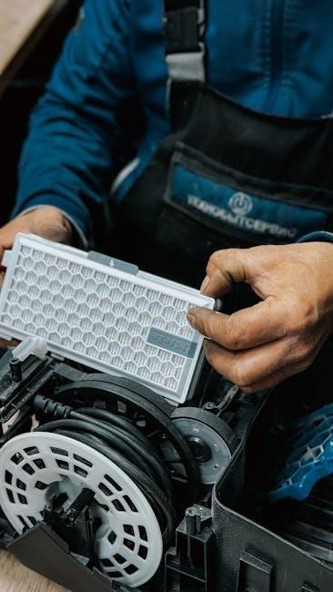
To replace the filter‚ first‚ locate the filter access panel on the air handler. Turn off the power to the unit before proceeding. Remove the old filter‚ noting the airflow direction indicated by the arrow on the filter frame; Insert the new filter with the arrow pointing in the same direction. Securely close the access panel; Consistent filter maintenance contributes significantly to the overall health and efficiency of your TEM6 system.
Common Issues and Solutions
Addressing common issues promptly can prevent further complications with your TEM6 air handler. One frequent concern is reduced airflow‚ often caused by a dirty air filter – replace it monthly or as needed. Another issue is ice formation on the refrigerant lines‚ indicating restricted airflow or low refrigerant levels; contact a qualified technician.
Unusual noises could stem from a loose blower wheel or motor; inspect and tighten components‚ or seek professional assistance. If the unit fails to power on‚ check the circuit breaker and power switch. For condensate drain blockages‚ clear the drain line with a wet/dry vacuum or drain cleaning solution.
Always prioritize safety and consult a qualified HVAC technician for complex repairs or refrigerant handling. Regular maintenance‚ as outlined in this manual‚ minimizes the likelihood of these issues and ensures reliable operation of your TEM6 system.

Technical Specifications
The TEM6 series offers diverse models‚ ranging from 2 to 5 tons‚ with detailed dimensional and electrical data available for installers and technicians.
Dimensional Data
Detailed dimensional data is crucial for proper TEM6 air handler installation‚ ensuring adequate space allocation and avoiding potential conflicts with existing infrastructure. The TEM6 series‚ designed for versatile placement – closets‚ utility rooms‚ basements‚ and attics – features varying physical footprints depending on the specific model and tonnage (2-5 tons).
Installers must consult the comprehensive specification sheets accompanying each unit to ascertain precise height‚ width‚ and depth measurements. These documents also outline critical clearances required around the unit for servicing and airflow optimization. Accurate measurements are essential for ductwork connections and electrical access points. Ignoring these specifications can lead to installation delays‚ reduced efficiency‚ and potential warranty issues. Always prioritize referencing the official documentation for the specific TEM6 model being installed.
Electrical Data
Understanding the TEM6 air handler’s electrical requirements is paramount for safe and compliant installation. The TEM6 series operates on specified voltage and phase configurations‚ varying based on model capacity (2-5 tons). Installers must verify the available power supply matches the unit’s nameplate data before commencing any electrical connections.
Critical electrical data includes minimum circuit amperage (MCA)‚ maximum overcurrent protection (MOCP)‚ and voltage tolerances. Improper wiring or inadequate circuit protection can result in equipment damage‚ fire hazards‚ and voided warranties. Always adhere to local electrical codes and regulations. Detailed wiring diagrams are provided in the installation manual‚ illustrating proper grounding procedures and low-voltage control wiring configurations. Qualified electricians should perform all electrical work‚ ensuring adherence to safety standards.

Warranty Information
The TEM6 series air handler is backed by a comprehensive warranty‚ protecting against manufacturing defects and component failures. This warranty coverage begins on the date of original installation‚ contingent upon proper installation performed by a qualified technician‚ adhering strictly to the guidelines outlined within this installation manual.
Warranty terms vary based on component type; typically‚ a standard five-year warranty covers the sealed refrigerant system‚ while a one-year warranty applies to parts. Registration of the unit within a specified timeframe (usually 60 days) is often required to validate the full warranty period. Proof of purchase and the completed warranty registration form are essential for any warranty claim.
This warranty does not cover damage resulting from improper installation‚ misuse‚ neglect‚ or acts of nature. Refer to the complete warranty document for detailed terms‚ conditions‚ and claim procedures.